
Galvanometer

A galvanometer is an instrument used to detect small(feeble) current in electric circuit. Galvanometer may be moving magnet galvanometer or moving coil galvanometer. In laboratory, a moving coil galvanometer is used.
When a current is passed through the coil, it experience a torque and deflects. The deflection of coil is directly proportional to the strength of current. A pointer attached to the coil shows a deflection under measuring skill. It is denoted by

Shunt
A low (small) resistance which is connected in parallel to a galvanometer is called shunt. It carries most of the current passing through the circuit and thus leaving a small amount of current to flow through galvanometer.
Uses:
1. It is used to for converting galvanometer into ammeter
2. It is used to prevent damage of galvanometer
3. It reduces decreases the total resistance of the circuit.
Conversion of Galvanometer into Ammeter
An ammeter is an instrument used to measure the current in electric circuit. It is connected in series. If large current is passed, the galvanometer may damaged. So when galvanometer is converted into ammeter, it measures current without any damage to it.
To convert galvanometer into ammeter of range 0 to IA, a small resistance S is connected in parallel to the galvanometer which is called shunt. Let G be the resistance of galvanometer and I be the maximum current measured by ammeter. Then `I_g` be the current flowing through galvanometer. Then (`I-I_q`) is the current passing through the shunts.

Since G & S are parallel combination,
P.d across S = P.d across G
This is the value of shunt. Knowing the value of `I_g`, I
and G, the value of S can be calculated. By connecting shunt of this value, the
given galvanometer can be converted into ammeter of the range 0 to IA.
The effective resistance `R_a` of the ammeter is given by
`\frac{1}{R_a} = \frac{1}{G} + \frac{1}{S}`
`\frac{1}{R_a} = \frac{S+G}{GS}`
`R_a = \frac{GS}{G+S}`
In practice, G is large as compared to S. Since S is low
resistance, equivalent resistance `R_a` of ammeter is very low and when it is
connected in series in circuit, it will not affect the current passing through
circuit.
Conversion of Galvanometer into an Voltmeter
A voltmeter is a device used to measure P.d. between two
points in a circuit. It is connected in parallel. Voltmeter should have very
high resistance ideally infinite resistance and must not change the current.
To convert a galvanometer into voltmeter of range 0 to V
volts, a high resistance R is connected in series to the galvanometer which is
called multiplier. The combination of galvanometer and multiplier for the
conversion of voltmeter is as shown in fig.
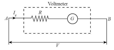
Let G be the resistance of the galvanometer and `I_g` be the
current flowing through galvanometer which produces the maximum deflection in
the galvanometer. Since high resistance R is connected in series with
galvanometer, same current `I_g` flows through Resistance R. The voltage across
the voltmeter is
`V = (I_g)(R+G)`
`V = (I_g)R + I_gG`
`I_gR = V – I_g G`
`R = \frac{V}{I_g} – G`
This is the value of resistance R. Knowing the value of V,
`I_g` and G, the value of R can be calculated. When the resistance of this
value is connected in series to the galvanometer, it will work as a voltmeter
of range 0 to V volt.
Eletrical Circuits
Kirchoff’s Laws:
First Law:
It states that the algebraic sum of currents at a
junction of circuit is zero.
Symbolically
`\sum I = 0`
Current flowing towards the junction as positive and current
flowing out from the junction as negative. Then applying Kirchoff’s 1st
law at the junction A, we have

`I_1 + I_2 + I_3 - I_4 - I_5 - I_6 = 0`
`I_1 + I_2 + I_3 = I_4 + I_5 + I_6`
Hence, the sum of current flowing towards the junction is
equal to sum of current flowing out from the junction.
Second Law
It states that in a closed loop, the algebraic sum of emfs
is equal to the algebraic sum of product
of current and resistance.
Symbolically,
`\sum E = \sum IR`
Explanation:

ABCA be a closed circuit whose sides AB, BC and CA carry
currents `I_1, I_2` and `I_3` respectively. The resistances of the sides are `R_1,
R_2` and `R_3` respectively. There is a cell of emf E in the circuit. In
complete circuit ABCA, we can write
`\sum E = \sum IR`
`I_1R_1+I_2R_2+I_3R_3=E`
If no cell in the circuit, E=0. So, we have
`I_1R_1 + I_2R_2+I_3R_3=0`
Wheatstone bridge
Wheatstone bridge is an electrical circuit which is used to
find the unknown resistance. It consists of four resistance P,Q,R & X in
which P,Q,R are known resistance and X is unknown resistance, when the battery
is connected across B&D then at balanced condition i.e. `I_g=0`
`\frac{P}{Q} =\frac{X}{R}`
This is the balanced condition for wheatstone bridge and
known as principle of wheatstone bridge.

Let, initially the circuit is not in balanced condition and
suppose `I_1 , I_2, I_3` and `I_4` be the current passing through P,X,Q and R
respectively. Then applying Kirchhoff’s first law at the junction B is
`\sum I = 0`
`I_1 – I_g – I_3 =0`
`I_1=I_g +I_3`
And at junction D,
`I_2 + I_g – I_4 =0`
`I_2 + I_g = I_4`
Applying Kirchhoff’s second law (voltage law) in loop ABDA
`\sum E = \sum IR`
`0 = I_1 P + I_g G – I_2 X`
`I_1 P + I_g G = I_2 X`
Similarly in closed loop BCDA,
`0 = I_2 Q – I_g G – I_4 R`
`I_3 Q = I_g G + I_4 R`
At balanced condition, the value of P, Q & R are so adjusted
that no current passes through the galvanometer i.e. `I_g= 0` then above eqn
becomes
`I_1 = I_3` and `I_2 = I_4`
And
`I_1 P = I_2 X`
`I_3 Q = I_4 R`
Dividing `eq^n` 6 by 7,
`\frac{I_1 P}{I_3 Q} = \frac{I_2 X}{I_4 R}`
From equation 5 & 8
`\frac{I_1 P}{I_1 Q} = \frac{I_2 X}{I_2 R}`
`\therefore \frac{P}{Q} = \frac{X}{R}`
This is required balanced condition of wheatstone bridge.
Meterbridge
Meterbridge is an electric device which is used to determine
the unknown resistance. It works on the principle of wheatstone bridge.
It consists of three metal strips of copper which are fixed
on wooden board. A constantan wire of uniform cross section and 1m length is
stretched tight between two terminal of meter scale as shown in figure

A resistance box R is connected in one gap and unknown
resistance ‘X’ is connected in another gap. A galvanometer is connected between
point D & jockey over the wire then resistance of AB = P and BC = Q
When the bridge is balanced then, wheatstone principle gives
`\therefore \frac{P}{Q} = \frac{X}{R}`
`\therefore (Resistance of AB)/(Resistance of BC) = \frac{X}{R}`
Let length of wire (AC) = 100cm and AB = l cm & BC =
(100-l) cm. Since the wire has uniform cross-section and `\rho` is constant
then its resistance is directly proportional to the length i.e. `P \alpha l`
and `Q \alpha (100-l)`
So,
`\frac{l}{100-l} = \frac{X}{R}`
`X = (\frac{l}{100-l})R`
By knowing the value of l, 100-l and R, the unknown resistance (X) can be calculated.
Potentiometer
Potentiometer is an electric device which is used to measure
the emf of cell and internal resistance, to compare the emf of two cell and
p.d. between two points. It is an ideal instrument for measuring the p.d.
between two points because it does not draw any current from circuit.

Potentiometer is a long wire AB and uniform cross sectional
area stretched between copper strips fixed on wooden board. The wire used in
potentiometer is manganin or constantan. The length of wire is
5-10m and each of the segment length is 1m. Driving cell is connected across point
A and B. The balanced point on wire is obtained by sliding the jockey over a
wire. At balanced point there is no deflection on galvanometer.
Principle: It is based on the principle that steady
current is passed through a wire of uniform cross sectional area, the p.d.
across any portion(segment) of wire is directly proportional to its length.
`V \alpha l`
Application:
1. To find the internal resistance of given test cell:

Experimental arrangement to find the internal resistance of
given cell using potentiometer is as shown in fig.
At first the key `K_1` is closed (with key `K_2` open) and
jockey is slided over the potentiometer wire till the galvanometer shows null
deflection. Suppose galvanometer shows null deflection at point `e` such that
`AC = l_1`. Since `l_1` is the balancing length for emf of test cell so.
Emf (E) = `V_AC = k l_1`
K is potential gradient.
Now a suitable value of resistance R is taken from the
resistance box and `k_2` key is closed. Then above process is repeated till the
galvanometer shows null deflection. Let galvanometer shows null deflection at
point D such that AD = `l_2`. Since `l_2` is the balancing length for terminal
p.d. of the test cell so terminal p.d.(V) =`V_AD` = `k l_2`
Dividing equation 1 by 2
`\frac{E}{V} = \frac{k l_1}{k l_2} = \frac{l_1}{l_2}`
Also expression for internal resistance of a source in terms
of its emf and terminal p.d. is
`r = R(\frac{E}{V} -1) = R(\frac{l_1}{l_2} -1)`
`\therefore r = R(\frac{l_1}{l_2} -1)`
By knowing the value of R, `l_1` and `l_2`, the value of
internal resistance of given cell can be determined.
2. Compare the Emf of given cells:

The experimental arrangement to compare the emf of given
cells is as shown in fig.
At first the test cell of emf `E_1` is connected in circuit
through the key `k_2` and jockey is slided over the potentiometer wire till the
galvanometer shows the null deflection. Let the galvanometer shows deflection
at point C such that AC = `l_1`. Then the emf of first cell is given by
`E_1 = V_AC = kl_1`
K is potential gradient
Now first cell is disconnected and the second cell of Emf
`E_2` is connected in the circuit through the key `k_2` and then repeat above
process till the galvanometer shows null deflection. Suppose galvanometer shows
null deflection at point D such that AD = `l_2`. Then emf of second cell is
given by
`E_2 = V_AD = kl_2`
Dividing equation 1 by 2
`\frac{E_1}{E_2} = \frac{k l_1}{k l_2}`
`\frac{E_1}{E_2} = \frac{l_1}{l_2}`
By knowing the value of `l_1` and `l_2`, the emfs of two
cell can be compared.
Post a Comment